We'll consider volume rendering of CT data on the GPU.
GPU Data
The volumetric data must be stored on the GPU:
- The attenuation values, $\tau[x,y,z]$, are
stored in a 3D texture of scalar values.
These values are typically 16-bit values in the range [0,1].
The texture is set up with an OpenGL call like
glTexImage3D( GL_TEXTURE_3D, 0, GL_R16, dimX, dimY, dimZ, 0, GL_RED, GL_UNSIGNED_SHORT, volumeTexMap );The
volumeTexMapabove is a 1D array ofdimX$\times$dimY$\times$dimZunsigned short integers that represent values in [0,1]. Note that these are in units of "attenuation per distance", so something will have to be done with the [0,1] range before using these values in the calculation. More on that later. - The gradients, $\nabla\tau[x,y,z]$, are pre-computed
using on of the methods
discussed earlier
and are stored in a 3D texture of 3-tuples. Each 3-tuple
contains the $x, y, z$ of the gradient.
Each of the $x, y, z$ components of the gradient is typically a 16-bit float value in the range [-1,+1].
The texture is set up with an OpenGL call like
glTexImage3D( GL_TEXTURE_3D, 0, GL_RGB16F, dimX, dimY, dimZ, 0, GL_RGB, GL_FLOAT, gradientTexMap );The
gradientTexMapabove is a 1D array ofdimX$\times$dimY$\times$dimZfloats, each in the range [-1,+1]. - The transfer function, $f: \tau \rightarrow
k_d, \tau'$ is stored in a 1D texture of 4-tuples. Each
4-tuple stores $k_d$ in its r,g,b components and stores
$\tau'$ in its $\alpha$ component.
The $\tau'$ must be a 16-bit value in [0,1] because that's what the original $\tau$ was. So all components must be 16-bit values in [0,1].
The texture is set up with an OpenGL call like
glTexImage1D( GL_TEXTURE_1D, 0, GL_RGBA16, 256, 0, GL_RGBA, GL_UNSIGNED_SHORT, transferTex );The
transferTexabove is a 1D array of any size containing 4-tuples of unsigned short integers. A larger array will provide more precision in the transfer function, but 256 (as above) is usually enough.Looking up in the texture at coordinate $\tau$ (which is in [0,1]) provides corresponding $k_d$ and $\tau'$.
Above the attenuation values and transfer function are stored on the CPU side as GL_UNSIGNED_SHORT. They could equally well be stored on the CPU side as GL_FLOAT. OpenGL will convert them to values in [0,1] in the textures, regardless of which format is used on the CPU side.
GPU Ray Casting
The volume is typically centred at the world origin with its axes aligned to those of the world. The viewpoint can be moved around the volume to generate different images.
The value in each pixel of the image is computed by
sending a ray from the eye to the pixel and then through
the volume.
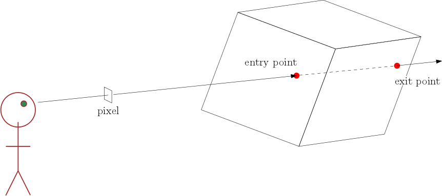
For the part of the ray inside the volume (between the two red dots above), the Discrete Volume Rendering Integral is evaluated: $$L_\textrm{out} = \displaystyle \sum_{i=0}^n C_i\ \alpha_i\ \left(\ \prod_{j=0}^{i-1}\ (1-\alpha_j)\ \right)$$
A separate fragment shader is used to compute $L_\textrm{out}$ for each separate pixel.
That fragment shader needs to know, for its own pixel, the following:
- The 3D texture coordinates at which the ray enters the volume.
- The 3D texture coordinates at which the ray exits the volume.
- The 3D world dimensions of the volume, so that the length of the ray segment between the entry and exit points can be computed.
- The slice spacing, so that the fragment shader can iterate along the ray segment in steps equal to the slice spacing.
- The direction toward the light, so that C can be computed.
The latter three values can be provided as "uniforms" to the fragment shader.
The first two values are more interesting and are discussed in the next section.
Determining Ray Entry and Exit Points
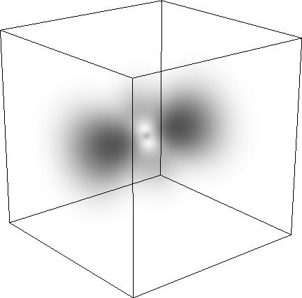
The volumetric data fits within a bounding volume, which has axis-aligned faces and which tightly fits the data. Below, the bounding volume is shown as a cube around the data from the electron density field of a hydrogen atom. (Even though some of the volume appears to be empty, it does have data which might be shown with a different rendering method.)
Suppose a ray is sent through a pixel into the volume above. Then the fragment shader for that pixel needs to know the 3D volume texture coordinates at the entry point and at the exit point.
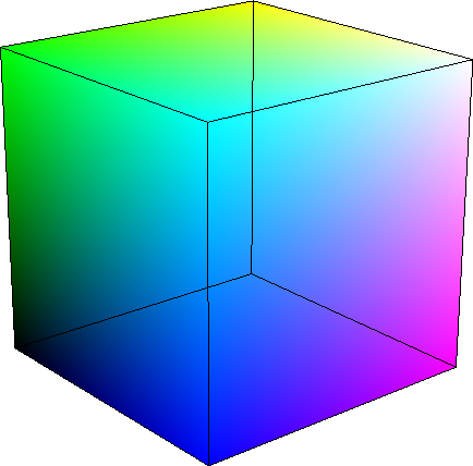
To compute the texture coordinates at the entry point, we can render the faces of the bounding volume with colours equal to the 3D texture coordinates of the volume texture, as shown below. This is done by assigning a colour to each vertex of the bounding volume and using OpenGL's "smooth" interpolation across the faces.
Below, for example, the black corner at the lower left has texture coordinates (0,0,0), the green corner at the upper left has texture coordinates (0,1,0), and the magenta corner at the lower right has texture coordinates (1,0,1).
Then the fragment can use its colour as the texture coordinates of the entry point.
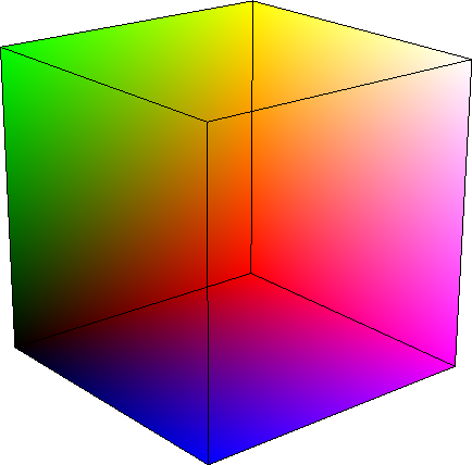
To compute the texture coordinates at the exit point, which is on the back of the bounding volume, we can render do the same thing, but only render those faces that are back-facing. This is done in OpenGL by "culling the front faces", which is achieved by calling
glEnable( GL_CULL_FACE );
glCullFace( GL_FRONT );
and then rendering the bounding volume as usual, with its vertices coloured by the texture coordinates. The result is an "inside view" of the bounding volume, as shown below.
Below, the red corner was previously hidden at the back of the volume. In this rendering, which has the front faces removed, the red corner is visible and has texture coordinates (1,0,0).
From this, you can see that the texture goes from (0,0,0) in the lower left, black, corner, to (1,1,1) in the upper right, white (although hard to see as white), corner. The axes of the texture coordinates have $x$ going from black-to-red, have $y$ going from black-to-green, and have $z$ going from black-to-blue. (These axes, in a texture, are usually called $s,t,u$ instead of $x, y, z$.)
Two-Pass Rendering
So that the fragment shader has both front and back texture coordinates, we'll draw the bounding volume in two passes:
- Pass 1: Draw the back faces of the bounding volume. In this pass, the output of the fragment shader is just the colour (i.e. the texture coordinates of the exit point) and that output is stored in a separate Framebuffer Object (i.e. a separate texture on the GPU).
- Pass 2: Draw the front faces of the bounding volume. In this pass, the fragment shader is given the texture coordinates of the entry point as a colour, and must look up in the Framebuffer Object at the fragment's position in the Framebuffer Object to get the texture coordinates of the exit point, which were stored in Pass 1.
Thus, in Pass 2, the fragment shader has the 3D volume texture coordinates of both the entry and exit points of the ray for which the fragment shader is responsible.
Given that information, along with the uniforms described earlier, the fragment shader can compute the Volume Rendering Integral for its ray. The output of the fragment shader is the result of that computation, and is used to colour the pixel through which the ray travelled.
Pass 2 Fragment Shader
The pass-2 fragment shader knows (as described above) the 3D texture coordinates, $s_\textrm{in}$, at the entry point and the 3D texture coordinates, $s_\textrm{out}$, at the exit point. It then has to evaluate the Volume Rendering Integral by iterating along the segment between $s_\textrm{in}$ and $s_\textrm{out}$ in steps of $\Delta s$, which depends on the slice spacing, $\Delta x$, and the spatial dimensions, $x_\textrm{dim}, y_\textrm{dim}, z_\textrm{dim}$, of the bounding box.
Note that $\Delta x$ is the slice spacing in world coordinates, while $\Delta s$ is the corresponding spacing in texture coordinates along that particular ray.
In the VRI $$L_\textrm{out} = \displaystyle \sum_{i=0}^n C_i\ \alpha_i\ \left(\ \prod_{j=0}^{i-1}\ (1-\alpha_j)\ \right)$$
the term $$t_i = \prod_{j=0}^{i-1}\ (1-\alpha_j)$$
denotes the total transparency up to step $i$. This is the amount by which the light, $C_i \; \alpha_i$, generated in the $i^\textrm{th}$ interval, is attenuated before leaving the volume through the entry point toward the eye.
At the entry point, $t_0 = 1$ because there is nothing in in front of the entry point to attenuate light on its way to the eye.
While stepping from entry point to exit point through the volume, this term can be incrementally updated. At the $j^\textrm{th}$ step, the update is $$t_j = t_{j-1} \times (1 - \alpha_j)$$
Exploiting this idea of incrementally updating the accumulated transparency, the fragment shader can compute $L_\textrm{out}$ as follows:
$L_\textrm{out} = (0,0,0)$
$t = 1$
for $s$ = $s_\textrm{in}$ to $s_\textrm{out}$ by $\Delta s$:
$\alpha = \tau(s) \; \Delta x$
$L_\textrm{out} = L_\textrm{out} + t \; C(s) \; \alpha$
$t = t \; (1 - \alpha)$
return $L_\textrm{out} + t \; L_\textrm{backlight}$
where $L_\textrm{backlight}$ is the light coming from behind the volume.
$\tau(s)$ is determined with a texture lookup in the 3D volume of attenuation values. If a transfer function is present, this must be followed by another texture lookup in the 1D transfer function to get $\tau'$ and $k_d$.
$C(s)$ is determined as described in the notes on Computing $C$ and $\alpha$, perhaps requiring a lookup into the gradient texture and perhaps using $k_d$ from a transfer function.
Warning: When stepping along the ray, the change in texture coordinates, $\Delta s$, must advance the spatial position on the ray by a distance equal to the slice spacing, $\Delta x$. The slice spacing is a spatial (i.e. world) measure; it is not a texture coordinate measure. Compute $\Delta s$ as follows: Given the spatial dimensions of the bounding volume, which is centred at the origin and aligned with the world axes, the spatial locations of the entry and exit points can be found from the texture coordinates, and the spatial segment between those two points can be divided into pieces of length equal to $\Delta x$. Then $\Delta s$ is the difference in texture coordinates between the start and the end of one of those pieces.
Rendering Modes
A volume can be rendered in different modes:
- With surface rendering, $C(s)$ is computed according to the Phong equation using the volume gradient.
- With digitally reconstructed radiographs (DRRs), $C(s) = (0,0,0)$ and only the backlight is attenuated by the accumulated $t$.
- With maximum intensity projections (MIPs), the output of the fragment shader is the opacity, $\alpha$, of the maximum-opacity interval along the ray.
The volume renderer can provide a "uniform" that tells the fragment shader which mode to use.