The MRI image shows the strength of the signal at each location in a transverse slice.
Recall from the Fourier Transform that any image can be written as the sum of images of sinusoidal waves at different directions, magnitudes, frequencies, and phase shifts.
Phase Encoding determines the magnitude and phase shift of every sinusoidal wave that makes up the MRI image. An inverse Fourier Transform is then applied to that data to reconstruct the MRI image.
Wavenumbers and Sinusoid Representations
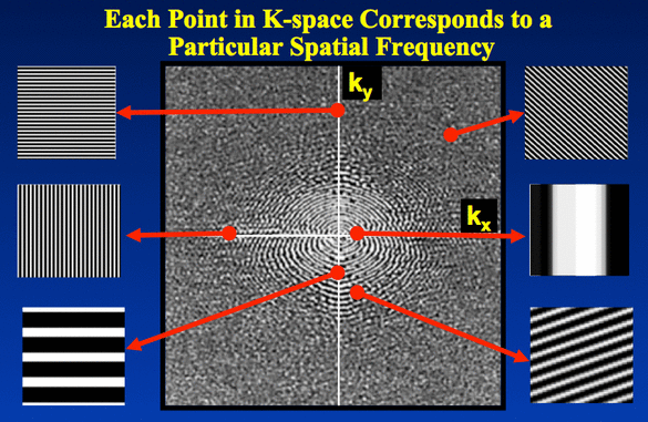
Recall that each point in the frequency domain (or "k-space" as it's called by MRI people) represents a sinusoidal wave in a particular direction with a particular frequency:

In an MRI image of $n \times n$ pixels (usually $n$ is 256 or 512) a sinusoid has wavenumber $\mathbf{k}$ if it has $k$ cycles for every $n$ pixels. So, for waves travelling left-to-right: with $k=1$, there is a single cycle across the whole image; with $k=2$, there are two cycles; and so on.
The sinuoid of wavenumber $k$ is $$\textrm{sinusoid}(x) = A \cos( {\textstyle {2\pi \over n}}\ k\ x - \theta )$$
for amplitude $A$ and phase shift $\theta$. Note that pixel positions $(x,y)$ have their origin near the centre of the image, so $x$ varies in $[ -{n \over 2}, {n \over 2}-1 ]$ from left to right in the image and $y$ varies similarly from bottom to top.
In 2D, $k$ is a vector in the frequency domain (going from the origin to one of the positions in the frequency domain) and the wave is $$\textrm{sinusoid}(r) = A \cos( {\textstyle {2\pi \over n}}\ k \cdot r - \theta )$$
Above, the $k \cdot r$ term is similar to the $r \cdot G_{xy}$ from the previous lecture and ensures that the sinusoid has the same value at all positions on any line perpendicular to $k$. So the sinusoid travels in direction $k$. The sinusoid has wavenumber $|k|$ because $|k|$ multiplies the distance of the projection of $r$ onto the line of $k$.
Look at some of the positions, $k$, in the image above and see how the direction and frequency depends upon $k$.
Representing Amplitude and Phase Shift
When representing the frequency domain on a computer, a point at position $k = (k_x,k_y)$ in the frequency domain stores a complex number, $c_k = a_k + i\ b_k$, that encodes the amplitude and phase shift of the sinusoid corresponding to that point.
More details are provided in the CISC/CMPE 457 notes (here and here), but the mapping between the complex value, $c_k$ and the sinusoid's amplitude, $A_k$, and phase shift, $\theta_k$, is $$\begin{array}{rl} A_k & = \displaystyle 2\ \sqrt{ \textrm{real}(c_k)^2 + \textrm{imag}(c_k)^2 } \\ \theta_k & = \displaystyle \arctan\left({ - \textrm{imag}(c_k) \over \textrm{real}(c_k) }\right) \\ \end{array}$$
It's not necessary to understand this mapping for CISC 472; it's sufficient to understand that the amplitude and phase shift of a sinusoid can be encoded as a complex number.