| Computed tomography (CT) | Magnetic resonance imaging (MRI) | Positron emission tomography (PET) |
|---|---|---|
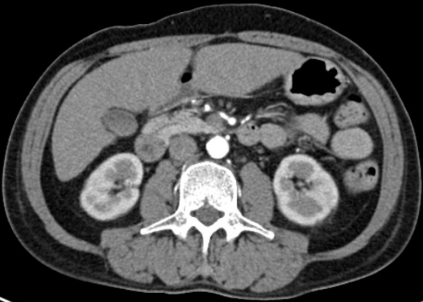 [radiopaedia.org] |
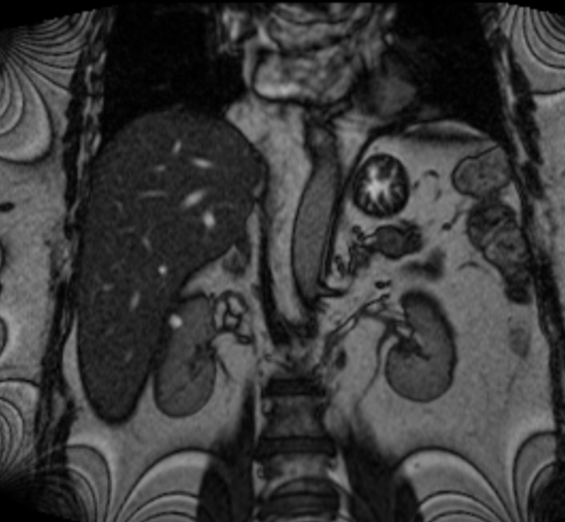 [radiopaedia.org] |
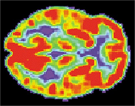 [wikipedia.org] |
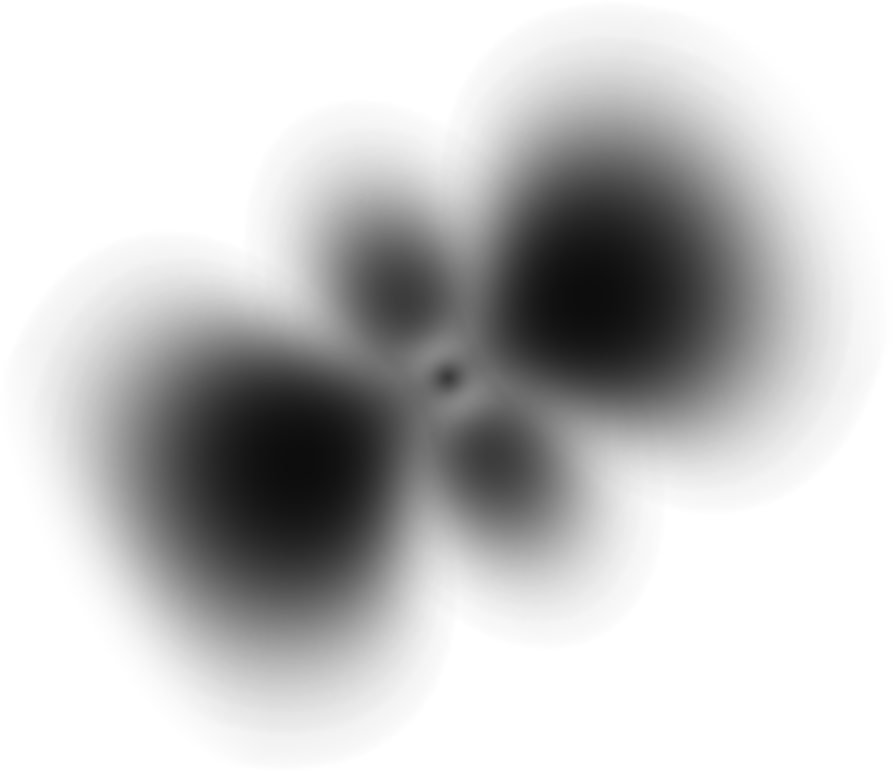
| Simulation | Analytical functions | |
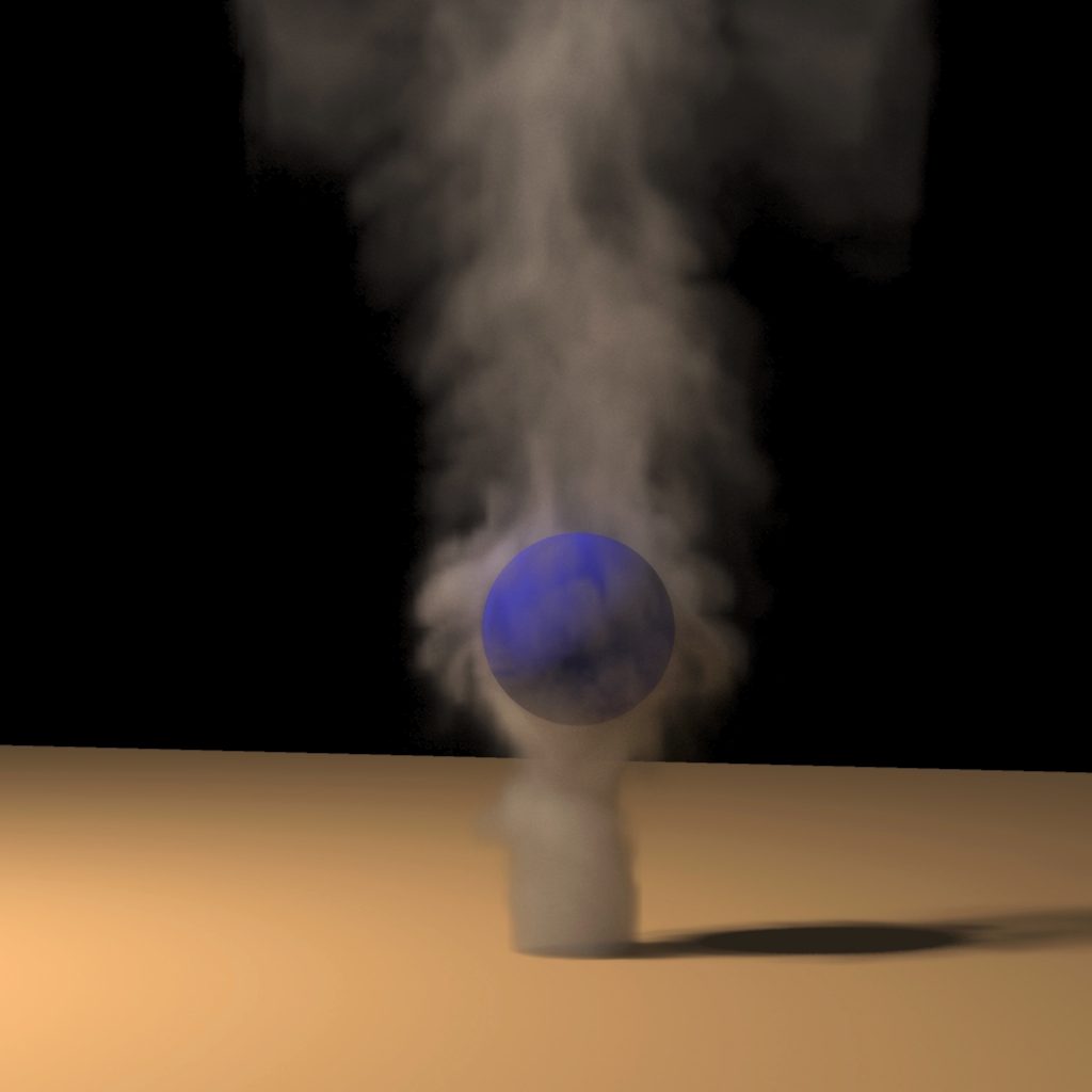 [Fedkiw, Stam, and Wann Jensen ] |
 |
| Computed tomography (CT) | Magnetic resonance imaging (MRI) | Positron emission tomography (PET) |
|---|---|---|
[radiopaedia.org] |
[radiopaedia.org] |
[wikipedia.org] |
| Simulation | Analytical functions | |
[Fedkiw, Stam, and Wann Jensen ] |
|
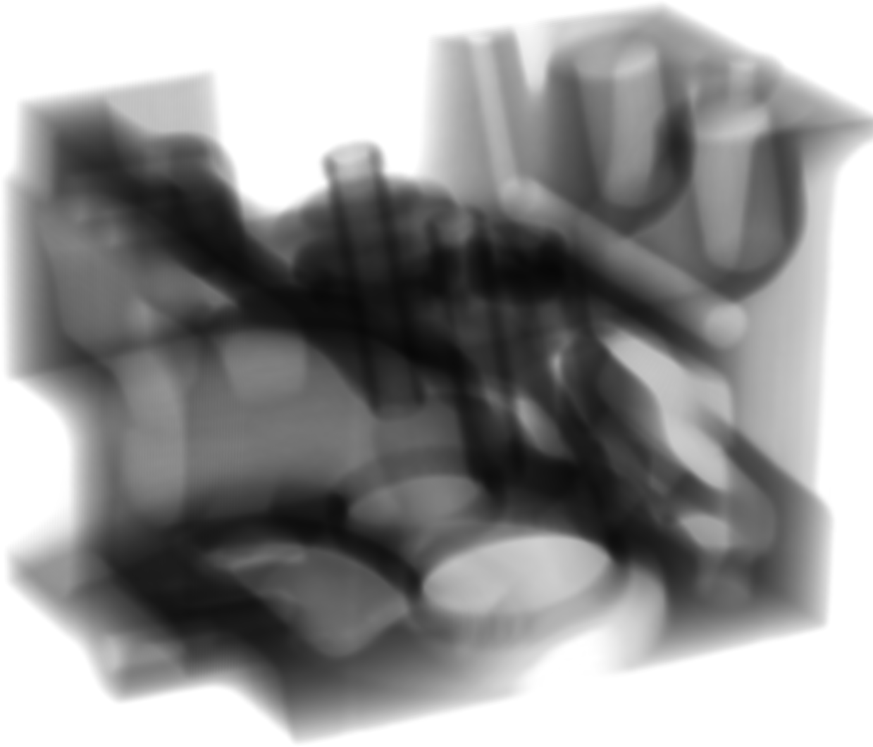
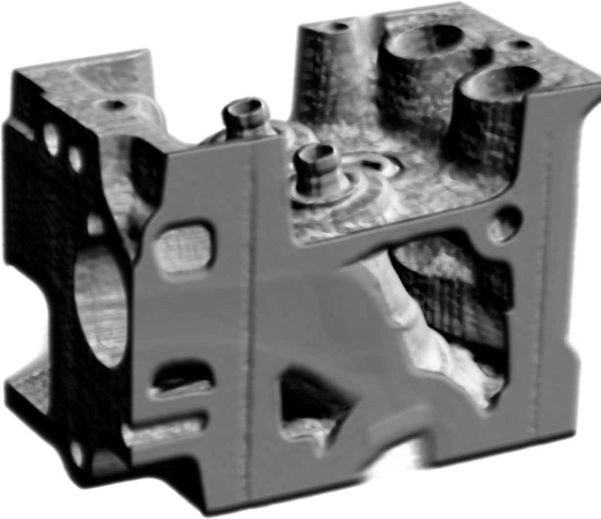
| Digitally reconstructed radiographs (DRR) | Surface rendering (Phong) | Maximum intensity projection (MIP) |
|---|---|---|
 |
 |
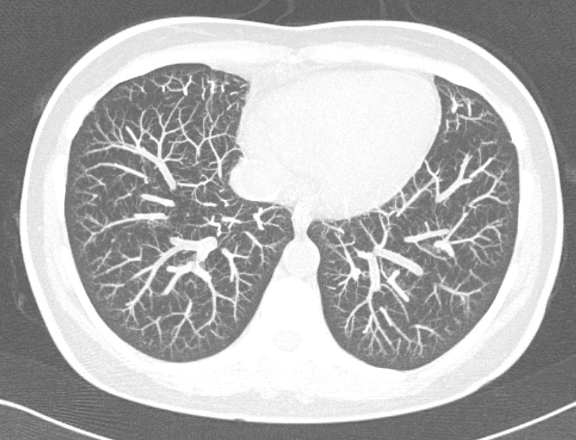 [radiopaedia.org] |
Volumetric data is organized in a 3D array of voxels:
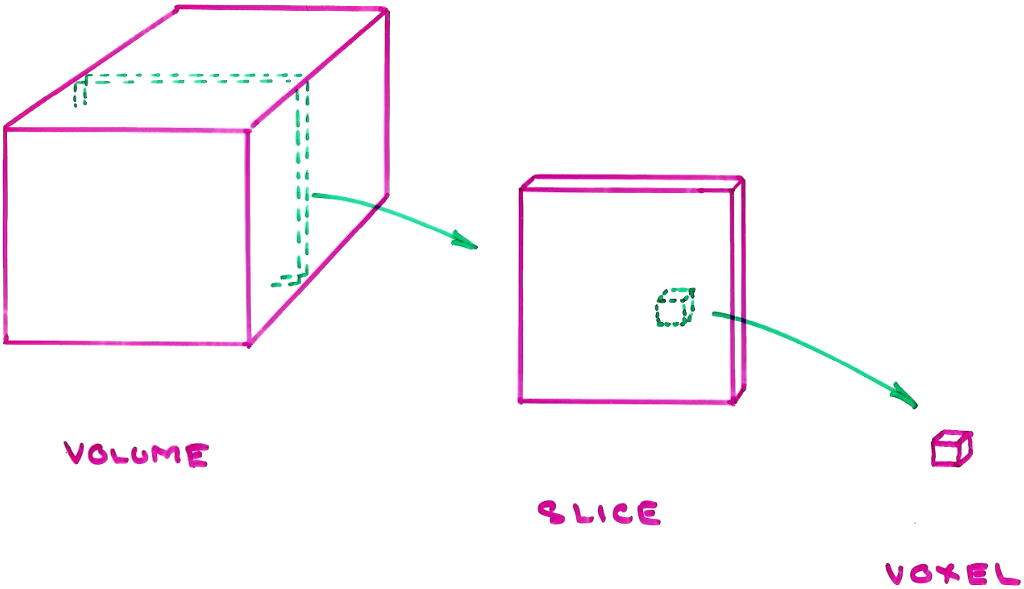
Each voxel stores a scanned value, like the "CT number", or several values, like the T1-, T2-, and PD-weighted MRI signals.
A voxel is not a cube. It usually has a square cross-section within a slice, but the inter-slice spacing is typically larger than the dimensions of the square. In most CT imaging, for example, the minimum inter-slice spacing is 0.625 mm (with 2 mm and 3 mm being more common) while the square cross-section might be as small as $0.25 \textrm{ mm} \times 0.25$ mm.
Direct volume rendering builds an xray-like image by computing the attenuation of xrays (i.e. photons) as they pass through the volume. This is commonly used for visuallizing CT data.
The resulting xray image is called a "digitally reconstructed radiograph", or DRR.
Photons passing through a volume interact with the volume; the volume is considered to be a participating medium, as it affects the photons passing through it.
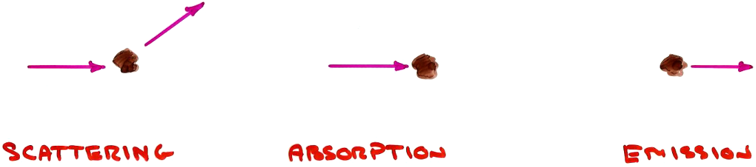
Interactions consist of:
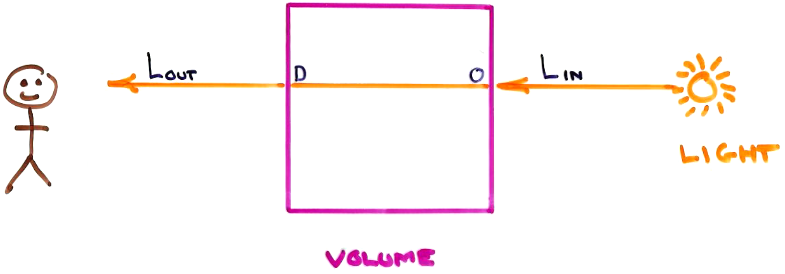
Absorption is governed by the equation $$\displaystyle\large \Lout = \Lin\ e^{-\int_0^D \tau(u)\ du}$$
where $\tau(u)$ is the fraction of light absorbed per unit length at $u$.
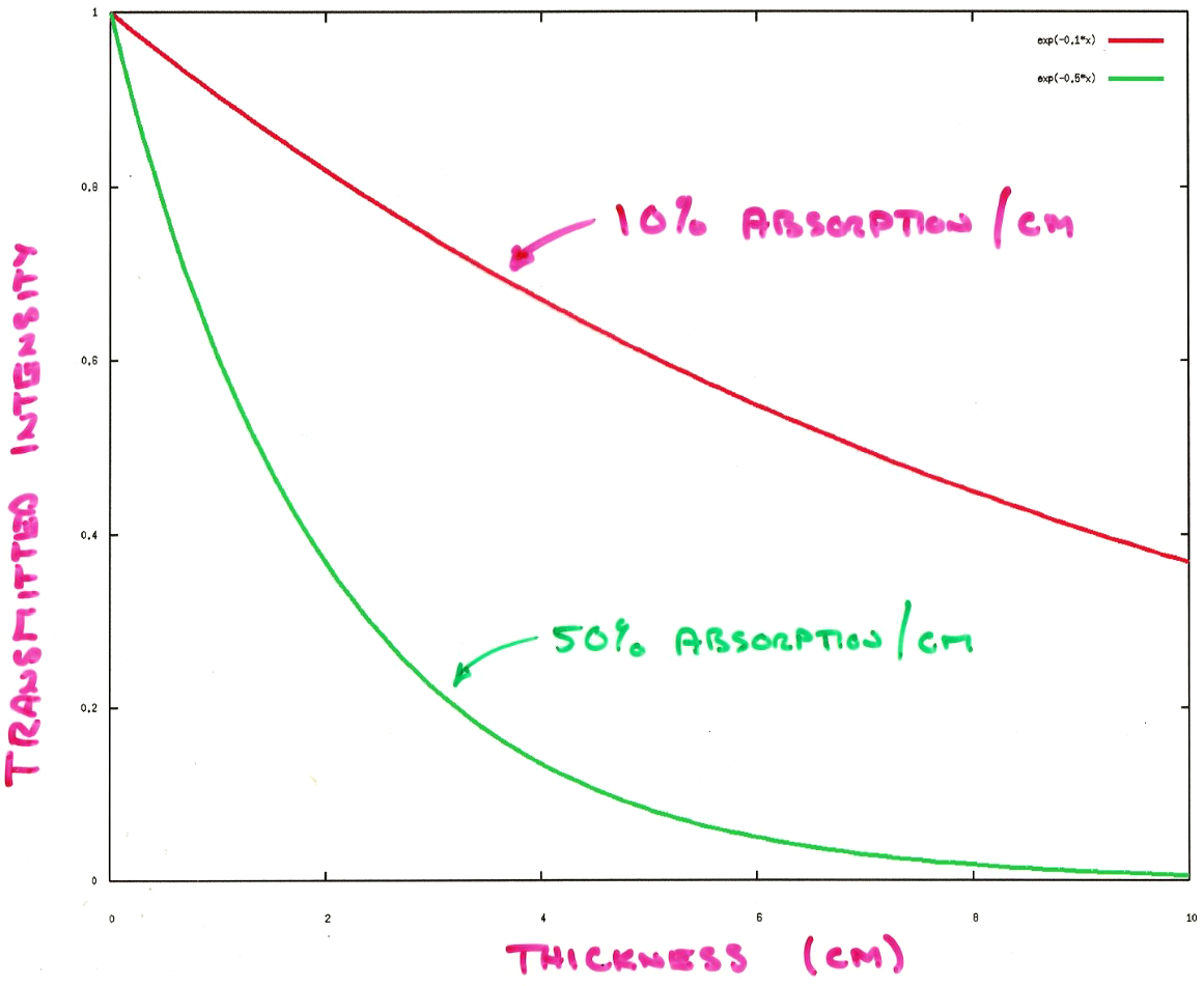
For a volume of constant absorption, $\tau$, light intensity decreases exponentially as it passes through the volume:
In CTs, each voxel stores a "CT number", $N_\mathrm{CT}$, which is $$N_\mathrm{CT} = {N - N_\mathrm{water} \over N_\mathrm{water} - N_\mathrm{air}} \times 1000$$
with $N$ being the xray absorption per unit length. $N_\mathrm{CT}$ is defined in "Hounsfield units", after one of the developers of CT imaging.
This is a bit deceptive, as the absorption rate actually varies with the xray energy and with the distance into the volume (due to an effect known as "beam hardening"). But most volume rendering methods assume that the CT number is constant for a particular material.
Some CT numbers are
| Material | $\mathbf{N_\mathbf{CT}}$ |
|---|---|
| air | -1000 |
| fat | -30 $\ldots$ -70 |
| water | 0 |
| soft tissue | 20 $\ldots$ 40 |
| bone | $>$ 1000 |
Claim: $\Lout = \Lin\ e^{-\int_0^D \tau(u)\ du}$
A fraction $\tau(s)\ \Delta s$ of $L(s)$ is absorbed over distance $\Delta s$ at location $s$:
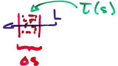
So $$- \Delta L = \tau(s)\ \Delta s\ L(s)$$
where $- \Delta L$ is the amount absorbed.
Converting the deltas into infinitesimals, we get $$\begin{array}{rcl} \displaystyle - dL &=& \tau(s)\ ds\ L(s) \\ \displaystyle {dL \over L(s)} &=& -\tau(s)\ ds \\ \displaystyle \int_0^D {dL \over L(s)} &=& \int_0^D -\tau(s)\ ds \\ \displaystyle \ln L(D) - \ln L(0) &=& \int_0^D -\tau(s)\ ds \\ \displaystyle \ln {L(D) \over L(0)} &=& \int_0^D -\tau(s)\ ds \\ \displaystyle {L(D) \over L(0)} &=& e^{\int_0^D -\tau(s)\ ds} \\ \displaystyle L(D) &=& L(0)\ e^{\int_0^D -\tau(s)\ ds} \end{array}$$
Emission from a point in the volume is used to simulate light reflecting off of a surface. The light is assumed to arrive at the point without any absorption. (If absorption on the way to the point were considered, we would get shadows cast through the volume from dense areas at the top of the volume.)
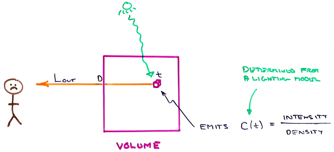
At position $t$, let $C(t)$ be the intensity of light emitted per "particle density". So a greater particle density will result in more light being emitted, as though it were emitted from, or reflected off of, more particles.
If rendering surfaces, we'll compute $C(t)$ using some local illumination model ... usually Phong.
Then $$C(t)\ \tau(t) = { \mathrm{intensity} \over \mathrm{density} } \times { \mathrm{density} \over \mathrm{length} } = { \mathrm{intensity} \over \mathrm{length} }$$
For an infinitesimal length, $dt$, at position $t$: $$C(t)\ \tau(t)\ dt = \mathrm{intensity}$$
So $$\Lout = \underbrace{C(t)\ \tau(t)\ dt}_{\textrm{intensity emitted at } t} \times \underbrace{\large e^{-\int_t^D \tau(u)\ du}}_{\textrm{attenuation from } t \textrm{ to } D}$$
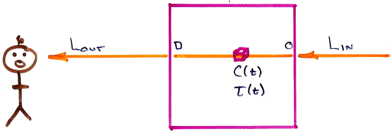
Combining the effects of absorption and emission, we get the Volume Rendering Integral: $$\LARGE \Lout = \Lin\ e^{-\int_0^D \tau(u)\ du} + \int_0^D C(t)\ \tau(t)\ e^{-\int_t^D \tau(u)\ du}\ dt$$
$\Lin$ in the "backlight" coming from behind the volume, while $C(t)$ is the surface shading of surfaces inside the volume. Surfaces typically occur in dense regions of the volume.
If $\Lin = 0$, we have a pure surface rendering.
If $C(t) = 0$ everywhere, we have a pure DRR.