Multipass Rendering
Forward shading is the standard technique which computes
pixel shading is a single pass:
- This can waste time doing computation on hidden pixels.
- This cannot achieve certain effects, such as cast shadows.
- This can be slow for certain effects, such as multiple lighting.
Deferred shading is a multipass rendering technique that
stores information or computes quantites in early passes, then
provides a pixel colour in the final pass. The final colour is
computed using the results from earlier passes.
- Deferred shading is used for cast shadows, for multiple lighting,
for non-photorealistic (NPR) effects, and other effects.
Deferred lighting is like deferred shading, but computes
specular and diffuse shading separately, then combines those in a
final pass.
OpenGL Framebuffer Objects
An OpenGL framebuffer object, or FBO, has multiple buffers
(i.e. arrays of data) and stores the output of the fragment
shader.
Each buffer has the same dimensions as the window. The output of
the fragment shader is stored in the buffer at the same
coordinates as the fragment in the window. The output of the
fragment shader is usually a colour, which is stored in the "back
colour buffer" at the fragment's position.
The default FBO has
- a front colour buffer (being displayed)
- a back colour buffer (being drawn into)
- a depth buffer to record the depth of the closest fragment
- a stencil buffer, if enabled
- an accumulation buffer, if enabled
An FBO can also contain any data buffers, which can hold
things such as normals, material properties, depths, and so on
between passes.
Depth Culling
The depth buffer is part of the FBO. The depth buffer, $D(x,y)$,
stores the depth of the closest fragment processed so
far, at each $(x,y)$ position. The depth is smaller for closer fragments.
Since many triangles in scene may overlap the pixel at $(x,y)$,
there may be many fragments that are processed at that pixel.
$D(x,y)$ is the depth of the closest of those many fragments that
have been processed so far.
When a fragment at position $(x,y)$ outputs a colour and/or data,
the fragment's depth, $d$, is compared to the value in the depth
buffer at the fragment's position. The fragment
is discarded if its depth is greater than or equal
to the depth stored in the depth buffer at the fragment's
position. In this case, its output values are not
written to the FBO.
if d >= D(x,y)
  discard fragment
else
  D(x,y) = d
If the fragment is closer than the closest fragment so far, its
depth, $d$, is written to the depth buffer and the fragment colour
and/or data are written to the FBO.
The depth test ensures that only the closest fragments are shown
on the screen after all fragments have been processed. These are
the fragments that are visible from the eye.

G-Buffers
A geometry buffer, or g-buffer, is another name for the
data buffers described above. A g-buffer stores information from
intermediate passes in textures on the GPU. These texture are
part of the framebuffer object.
The fragment shader can output to these textures, rather than to the
usual back colour buffer.
The fragment shader also can read from these textures. To do so,
the fragment shader needs to know its screen-space coordinates,
$(x,y)$, in $[0,1] \times [0,1]$, so that it reads from the
correct position (i.e. the fragment's position) in the texture.

G-buffers typically store colour, normals, depth, but can also
store $k_s$, $n$, and other material properties.
Example: Phong shading
Create g-buffers that are the same dimensions as the window to
store $k_s$, $k_d$, and $n$ (the specular exponent), and the
normal $N$. These are set up with OpenGL in a framebuffer object
- Pass 1:
Render the scene and store the material properties and $N$.
Just as the GPU shows only the fragment closest to the eye
(using its z-buffer depth testing), the GPU keeps only the
material values that correspond to the closest fragments.
So, after pass 1, the g-buffers will contain the material
properties of the fragments closest to the eye.
- Pass 2:
Render a single quad over all the pixels on the screen. This
causes a fragment to be created for each pixel, and a
corresponding fragment shader to be executed.
The fragment shader looks up the material properties,
computes Phong illumination, and outputs the resulting colour
to the framebuffer for display.
This two-pass rendering means that the Phong computation will
be done only for visible pixels. With the usual "forward
rendering", that computation is done for all fragments,
including potentially many, many hidden fragments.
The FBO in pass 1 had buffers for the $k_s$, $k_d$, $n$, and
the normal, $N$. The FBO in pass 2 was the default FBO, since the
output of the pass 2 fragment shader was displayed on the window.
Note that the depth test can be disabled in pass 2 because only
a single quad is being drawn on the screen, so there is exactly
one fragment for each pixel.
Rendering Cast Shadows
Cast shadows are shadows that are cast from one object
onto another, or from one part of an object onto itself.
Self-shadowing occurs when the surface points away from
the light, causing it to be darker.
Cast shadows can be rendered with deferred shading, using two
passes:
- Pass 1:
Render the scene from the viewpoint of the light source. In a
g-buffer, $G$, record the depth of each fragment from
the light source. This depth is in the range $[0,1]$.
- Pass 2: Render
the scene again, but from the real viewpoint.
Each fragment will need to know its 3D position in the
world coordinate system, so the vertex shader should compute
the vertex's world coordinates and pass them to the fragment
shaders as smooth variables.
In the fragment shader, transform the world coordinates of
the fragment into the clipping coordinate system of the
light. From that determine the fragment's depth, $d$, in
the range $[0,1]$. Also determine the position, $(x,y)$, of
the fragment in the range $[0,1] \times [0,1]$.
Look the depth recorded in $G(x,y)$. That is the depth of
the closest fragment seen by the light at position $(x,y)$,
which is the position of the current fragment. If the
depth, $d$, of the current fragment is greater than
$G(x,y)$, there is another fragment that is closer to the
light, so the current fragment is in shadow and its output
colour should be made dimmer.
If the light is directional, orthographic projection should be
used to transform world points into the clipping coordinate system
of the light. If the light is a point source, perspective
projection should be used.
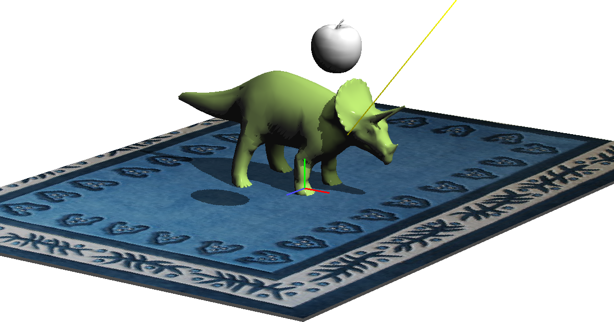
Below: The scene with a yellow line from a directional light.
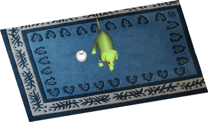
Below: The scene rendered from the light source using
orthographic projection. All of the shadows are hidden
underneath the objects.
Below: The depth buffer as rendered from the light source using orthographic projection. Darker fragments have smaller depth, so are closer.

up to Schedule & Notes