To reconstruct a CT slice from the sinogram, backproject the absorption profile across the image:
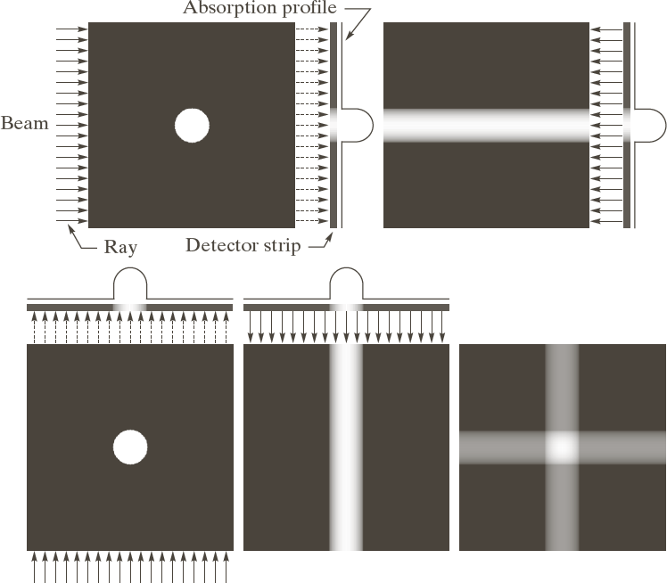 [Gonzales & Woods]
The image gets better with more backprojections:
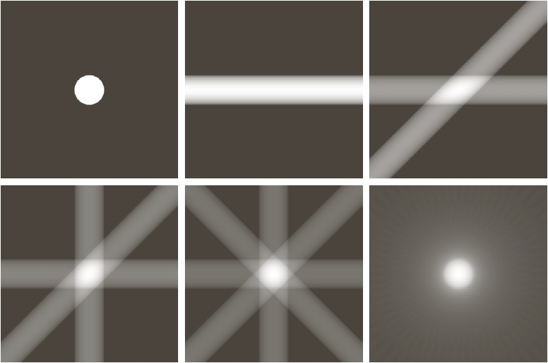 [Gonzales & Woods]
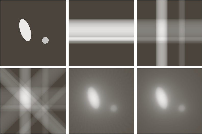 [Gonzales & Woods]
To compute the value at $f(x,y)$ in the image, $f$, determine the corresponding points in the absorption profile, $g(\theta,\rho)$, that $f(x,y)$ projects to. Then backproject all of these $g(\theta_i,\rho_i)$ onto $f(x,y)$.
Here's the relation between $(\theta,\rho)$ coordinates in the absorption profile and $(x,y)$ coordinates in the image:
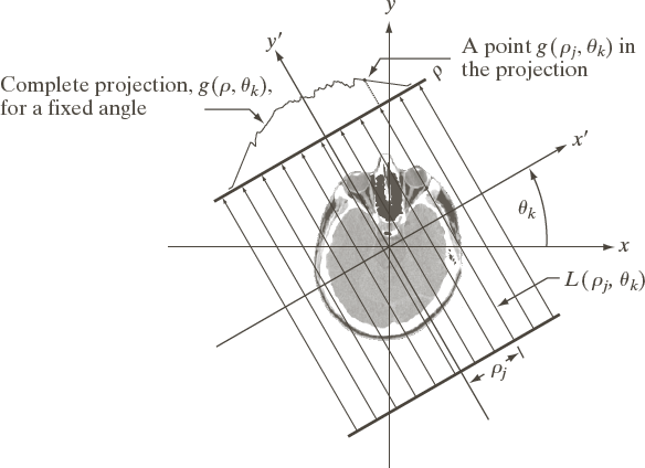 [Gonzales & Woods]
Point $(x,y)$ projects to $\rho = x \cos\theta + y \sin\theta$ in the absorption profile at angle $\theta$. (Here's a vector review to support this claim.)
So the value at $(x,y)$ in the image, $f$, is
$f(x,y) = \sum_{\theta_i} \; g(\theta_i, x \cos{\theta_i} + y \sin{\theta_i} )$
Here's how $f(x,y)$ gets reconstructed as we step through the angles, $\theta_i$, and sum up the contributions at each $f(x,y)$:
The problem is that the image is "blurry" and objects have halos around them.
The solution is to filter each row of the sinogram to suppress the low-frequency components and enhance the high-frequency components.
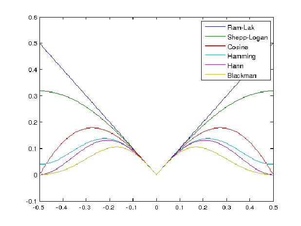
This can be done with a filter. In the frequency domain, common filters are the Ram-Lak filter (for Ramachandran and Lakshminarayanan) and the Hamming-windowed Ram-Lak filter:
 []
[]
The Ram-Lak filter is the "correct" filter for accurate backprojection with infinite sampling and zero noise. This can be shown through an analysis of the reparameterization of $g(\theta,\rho)$ in the frequency domain.
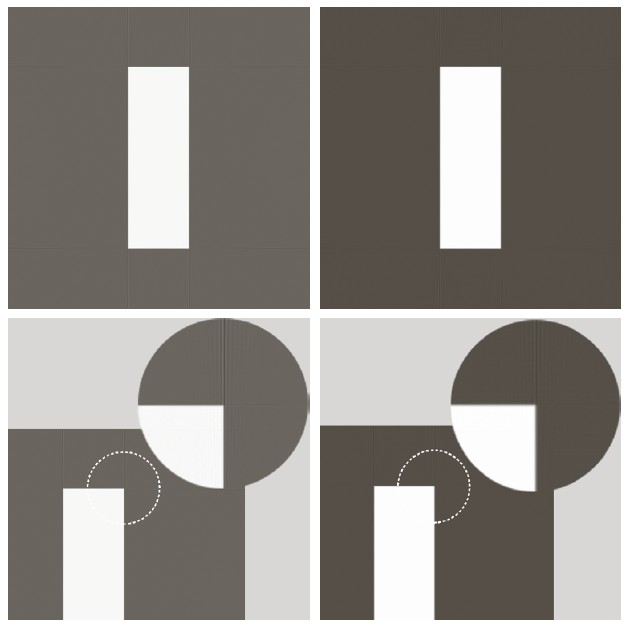
However, the Ram-Lak filter has sharp edges when a finite number of sample is taken (as with CT). This leads to echos (or "ringing") in the reconstructed $f(x,y)$. And the high-frequency components of the Ram-Lak filter will cause noise in $g(\theta,\rho)$ to be enhanced.
To reduce this phenomenon, the high-frequency parts of the Ram-Lak filter are attenuated by multiplying the Ram-Lak filter with a windowing function, such as the Hamming window.
The left column below shows ringing with the Ram-Lak filter, while the right column shows reduced ringing with the Hamming-windowed Ram-Lak filter:
 [Gonzales & Woods]
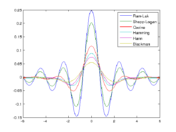
This filtering is accomplished on $g(\theta,\rho)$ by convolving the corresponding spatial-domain filter with $g(\theta_i,\rho)$ for each $\theta_i$, separately.
These are the spatial domain filters (i.e. inverse Fourier transforms) of the frequency domain filters shown above:
 []
[]
Here's what happens to each row, $g(\theta_i,\rho)$ of the sinogram when convolved with a filter:
Then the backprojection yields a sharper image:
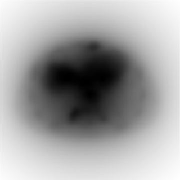
This is a substantial improvement over unfiltered backprojection:
 |
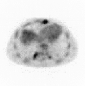 |
| Unfiltered backprojection | Filtered backprojection |