 [ Gonzales & Woods figure 8.34 ]
With predictive encoding, the previous pixels in the stream are used to predict the value of the next pixel or pixels. This is used in JPEG and PNG images and in MPEG video.
Differential pulse-code modulation (DPCM) is the name of the technique in which, instead of transmitted the next value, $x_i$, we transmit its difference with the previous value:
For $x_i$, output $x_i - x_{i-1}$.
With DPCM, $x_{i-1}$ is being used to predict $x_i$ and only the error in the prediction is being encoded.
A stream of such differences will have smaller values, which can be better entropy-encoded.
Let $\widehat{f}(x,y)$ be the encoding of pixel value $f(x,y)$. With DPCM, $$\widehat{f}(x,y) = f(x,y) - f(x-1,y)$$
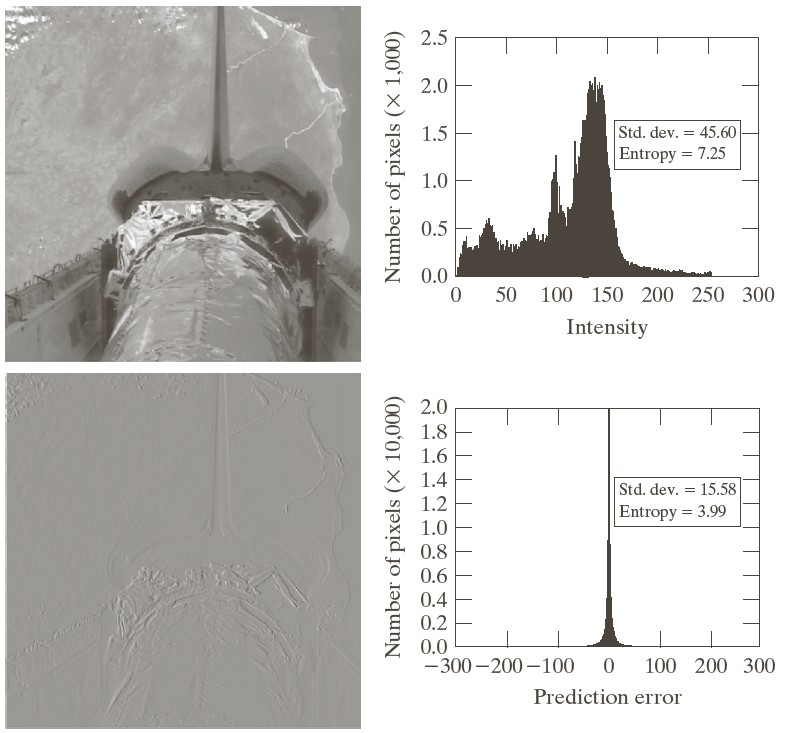
The figure below shows an image of the space shuttle in the upper left, and its DPCM encoding in the lower-left. The right images show the corresponding histograms.
 [ Gonzales & Woods figure 8.34 ]
This can also be done in 2D, where pixels are output left-to-right and top-to-bottom. At pixel $(x,y)$, the pixels above and left have already been output, so are available to use in a prediction. This is typically done as $$\widehat{f}(x,y) = f(x,y) - \Big( a\ f(x-1,y-1) + b\ f(x, y-1) + c\ f(x-1,y) \Big)$$
where the weights $a$, $b$, and $c$ can be chosen.
For example, the PNG image format allows the image to specify the encoding and has these options:
| Option | $\mathbf{a, b, c}$ | |
|---|---|---|
| none | $0, 0, 0$ | |
| sub | $0, 0, 1$ | |
| up | $0, 1, 0$ | |
| average | $0, \frac12, \frac12$ | |
| Paeth | -1, 1, 1 | (with special program code) |
All PNG calculations are done on bytes and taken "mod 256". Note that the "sub" option is DPCM.
"3D" usually refers to video, having three coordinates which include time. Here are two adjacent frames of a video:
We could use the previous frame to predict the next frame, like $$\widehat{f}(x,y,t_i) = f(x,y,t_i) - f(x,y,t_{i-1})$$
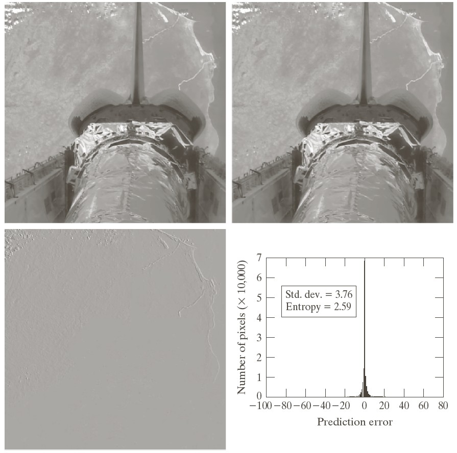
The figure below shows in the top row two adjacent video frames from a camera mounted on the space shuttle, with the earth rotating underneath. The DPCM encoding is shown in the lower-left, where pixels of the shuttle are well predicted, but those of the earth less so because of its movement with respect to the camera.
 [ Gonzales & Woods figure 8.35 ]
To compensate for motion, the MPEG video format tracks the motion of $8 \times 8$ or $16 \times 16$ blocks of pixels, called macroblocks.
Pixel values are predicted from the same macroblock of the previous frame, as described above, but the macroblock is shifted by some $(\Delta x, \Delta y)$ before the prediction is used.
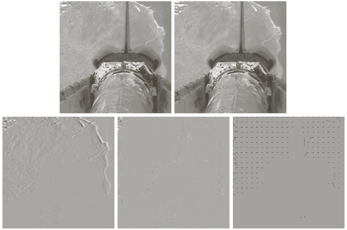
The figure below shows on the top row two adjacent video frames of the space shuttle.
The bottom row shows (left) uncompensated predictive encoding, (middle) motion-compensated predictive encoding, and (right) the $(\Delta x, \Delta y)$ shift of each macroblock as a small arrow. Note that macroblocks of shuttle pixels are not shifted.
 [ Gonzales & Woods figure 8.37 ]
More recent versions of MPEG allow fractional pixel shifts of the macroblock, smaller macroblocks, and even allow a macroblock to be partitioned, with different shifts in each partition.
Finding the optimal shift of a macroblock (i.e. which best predicts pixels in the following frame) is an expensive search process. But that's okay because this is done in the encoder; the decoder is still very fast.
Frames in an MPEG video are of three types:
A frame sequence might look like $$I\ P\ B\ P\ B\ I\ P\ P\ B\ P\ B\ P\ I$$
"B" frames require that the previous and next frames be received before they can be decoded, so frames have to be buffered.
The longer the distance from "I" frames, the more error accumulates in "P" frames, but the exact sequence of frame types will depend upon the characteristics of the frames.